
1
2
3
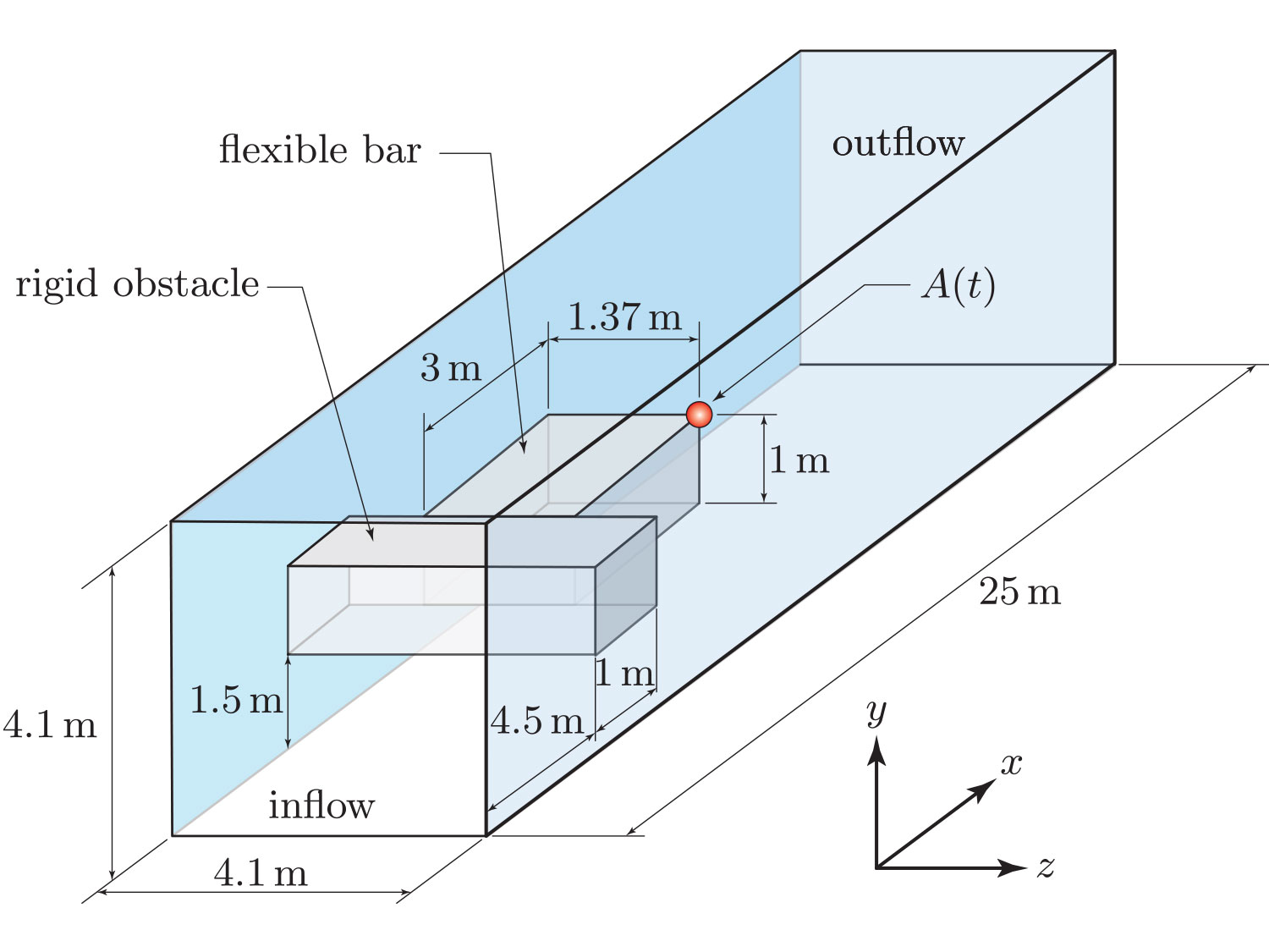
Fig. 1
Configuration of 3D benchmark. The results of the simulation consists in tracking the displacement of the point A(t) in the figure and in determining the hydrodynamic forces acting on rigid obstacle and flexible bar system.
Fig. 2
Vertical channel containing viscous fluid through which a small incompressible disk is descending: (a) system’s geometry; (b) initial conditions (disk released from rest in a quiescent fluid); (c) detail of mesh of the immersed body. The disk’s terminal velocity is denoted by Ut.
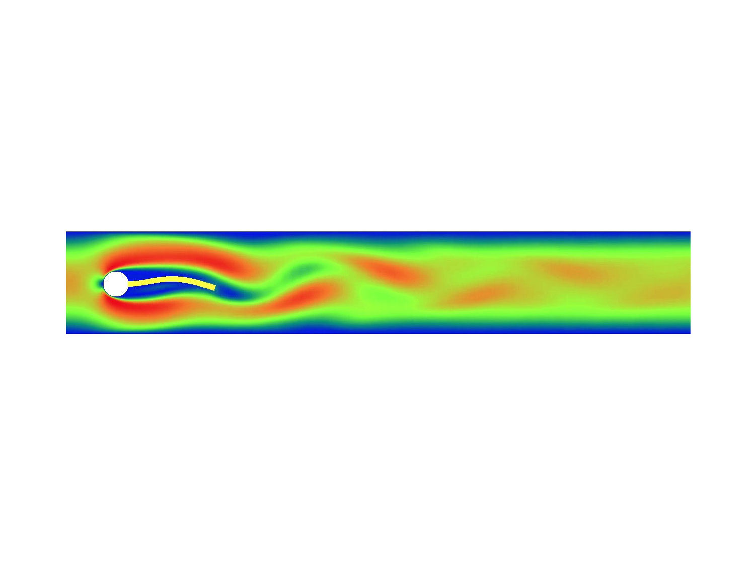
Fig. 3
Frame from animation showing the motion of a flexible flag as described in the FSI 2 benchmark by Hron and Turek.