
1
2
3
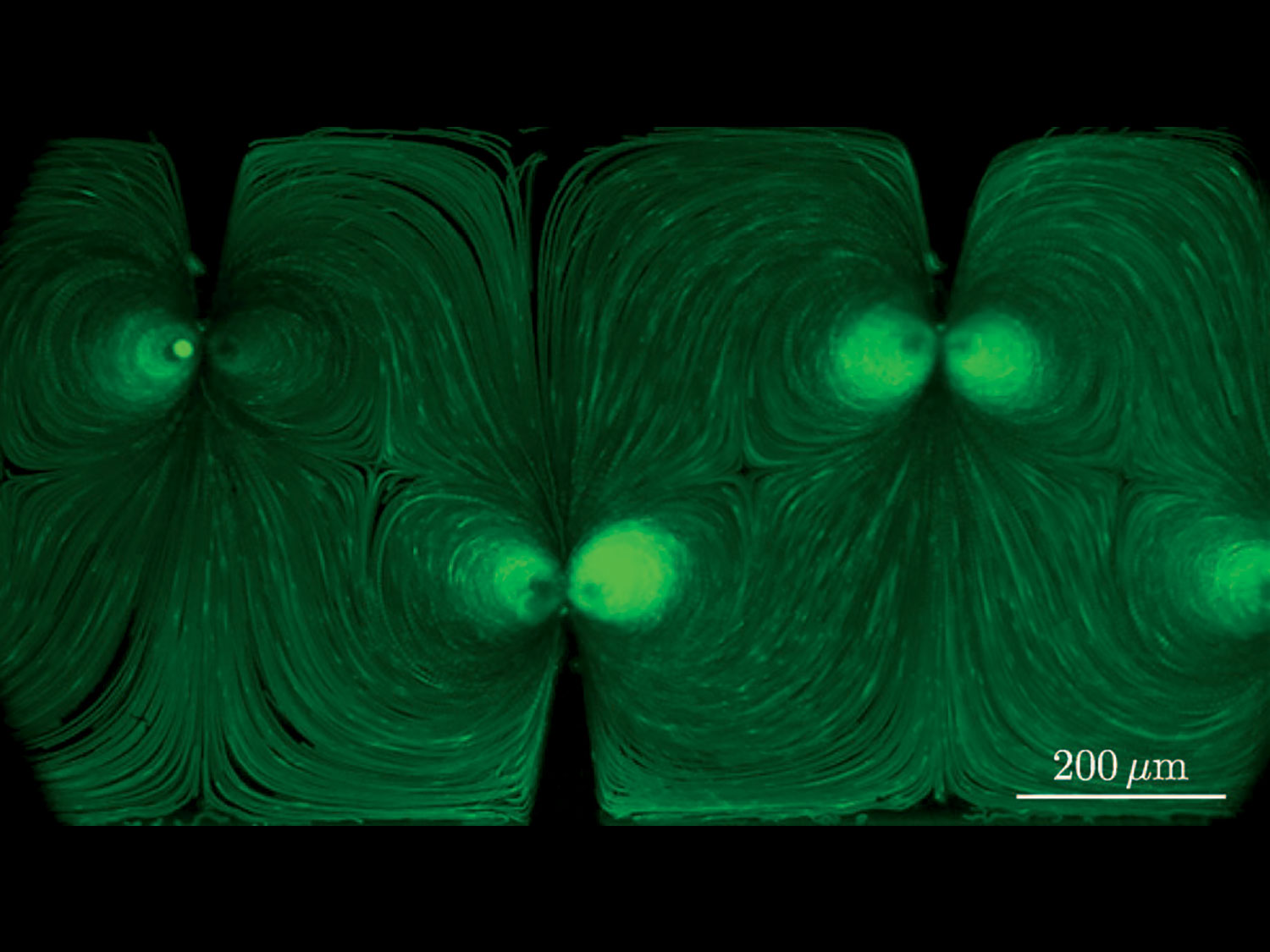
Fig. 2
Experimentally observed trajectories of 1.9 μm diameter fluorescent polystyrene beads in our acoustically oscillated micro-mixer with sharp edges. The geometry of the microchannel is described in Fig. 1(c) except for the fact that here, the tips of the sharp edges are 200 μm from the wall instead of 250 μm. The driven oscilla- tion is harmonic with a frequency equal to 4.75 kHz.
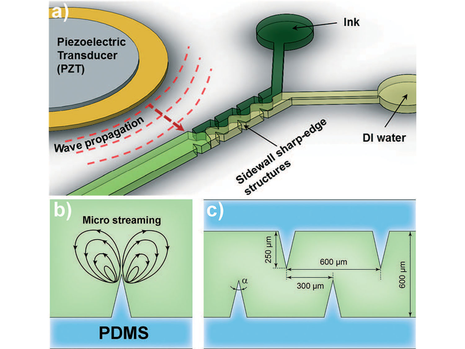
Fig. 1
(a) Schematic of the device showing a microfluidic channel with sharp-edge structures on its side walls. The channel walls are subjected to a time-harmonic excitation produced by a piezoelectric transducer placed on one side of the channel. (b) Typical micro streaming patterns produced in the fluid occupying the channel as a response to piezoelectric excitation. (c) Typical geometric dimensions of the corrugated channel.
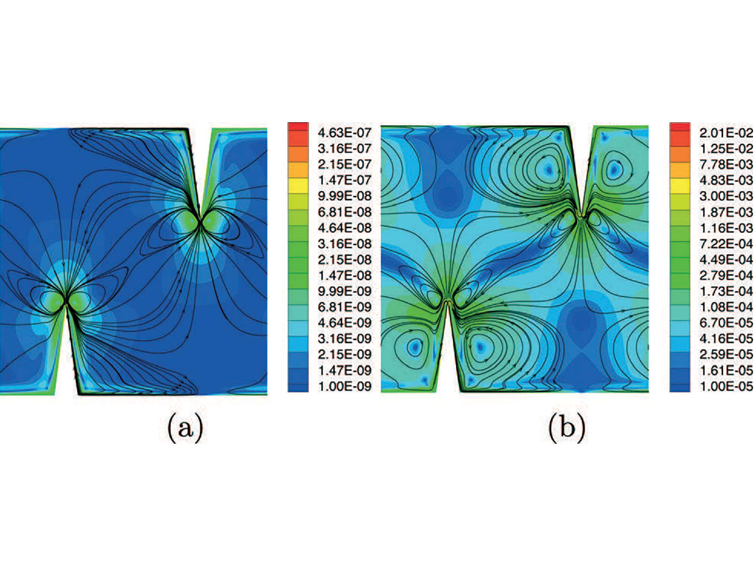
Fig. 3
Plots of the velocity vbead in Eqn (20) corresponding to the boundary conditions in (a) eqn (14) and (b) eqn (15). The color map represents the magnitude of vbead whereas the lines are some of the streamlines of the vbead field. The channel dimensions are L = 300 μm (horizontal dimension), H = 600 μm (vertical dimension), α = 15° (sharp edge angle), and h = 200 μm (height of the sharp edge). The wall displacement was only in the vertical direction with magnitude 1 μm.